Digitizer View
Configure the DMM's sampling and triggering settings for digitizing.
Digitizer view is available for the 34410A, 34411A, 34460A, 34461A, 34465A*, 34470A*, DM34460A, and DM34461A DMMs only. In Digitizer view, the DMM controls triggering and measurement start/stop/interval. Readings are stored in the DMM's internal memory. When measurements are complete, the readings are uploaded, displayed, and saved to a data log on the computer.
* PathWave BenchVue DMM application supports digitizing on the 34465A and 34470A DMMs without the Digitizing Option (Option DIG) installed in the DMM. Note, however, that an internal trigger source and pre-trigger count are not supported in PathWave BenchVue DMM application without the Option DIG firmware license installed in the DMM. This license is separate from the PathWave BenchVue DMM application license and both licenses must be installed to use the full set of digitizing features in PathWave BenchVue DMM application.
About Digitizing...
DMMs can be used to digitize low-frequency input signals by setting the measurement function to DCV on a fixed range, auto zero off, and NPLC or aperture time to a low value, to achieve the fastest sample rate. With these settings, the DMM's integrating A/D converter approximates a sampling A/D converter. To avoid aliasing when digitizing using the DCV function, the highest frequency component of the input signal should be less than half the DMM's sample rate (Nyquist frequency). For example, if the DMM's sample rate is 50 ksamples per second, the maximum frequency component of the input signal should be less than 25 kHz. Refer to these application notes for details and important notes about digitizing with a DMM:
Data Logging and Digitizing Using a Digital Multimeter
Understanding Dynamic Signal Analysis
Data Log Name
The default file name consists of the DMM model number followed by "Data Log", the date, current time, and a numeric index. For example, 34411A Data Log 2021-09-20 11-40-26 31.
For example – C:\Users\<user_name>\Documents\Keysight\PathWaveDMM\Data Logs\.
To change the default name, click  to open the file name editor. You can edit the prefix name and also have the option to include or exclude the date, current time, and numeric index. The date is in the form YYYY-MM-DD and the time is in the form HH-mm-ss (24-hour time format). For example, <model> Data Log 2021-09-20 11-40-26 31 – September 20, 2021 at 11:40:26 a.m. with a numeric index of 31.
- If included, the date, time, and numeric index fields are automatically updated with each subsequent data log operation from this application.
- The date and time fields are based on your computer's internal clock setting.
- The data log is stored with a .IVIF file extension.
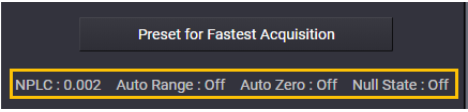
Preset for Fastest Acquisition
Preset the DMM to the specific configuration that enables the fastest acquisition of readings. The status line below the button show the settings selected for your specific DMM model.
Total Samples (calculated)
Calculated based on the samples/trigger, trigger count, and pre-trigger samples (see Trigger Settings below) . You can manually enter a Sample Count in this field, which will change other settings in this panel – the Samples/Trigger value is set to the same value as the Sample Count and the Trigger Count is set to "1".
Acquisition Time (estimated)
Calculated based on the selected delays, timers, and trigger intervals. Since the pre-trigger count (see Trigger Settings below) is not always satisfied at the time the trigger condition occurs, the actual acquisition time may be different from the calculated value – therefore, the minimum time is shown here.
Sample Settings
When your application requires that more than one sample be acquired each time a trigger condition is met, you must set the timing between the samples. For example, you can configure the DMM to automatically determine the sample timing based on the aperture time plus the trigger delay. On some modern DMM models, you can also set the sample timing using an internal timer. In this case, you can enter the sample timing as either sample interval (time between samples) or sample rate (the inverse of the sample interval).
Samples/Trigger
Set the number of samples to be acquired per trigger.
Pre-Trigger Samples
Set the number of samples to be acquired while waiting for the specified trigger event to occur. When the trigger event occurs, the buffered readings are transferred to reading memory and the remaining readings are recorded as usual.
Sample Timing
Set the sample timing when the sample count is greater than one. Depending on your specific DMM model, you can set the sample timing using one of the following methods:
- Sample Time + Trigger Delay - Set the sample timing as the sum of the aperture NPLC and the specified trigger delay.
- Sample Interval - Set the sample interval (time between samples) in seconds or click "Set Min Sample Interval" to select the minimum interval for the current configuration.
- Sample Rate - Set the sample rate in samples/second or click "Set Max Sample Rate" to select the maximum rate for the current configuration.
Trigger Settings
Set the triggering parameters for the measurements.
Trigger Source
Select the trigger source for the measurements.
- Immediate - Start auto-triggering as soon as the trigger source is selected.
- Internal - Trigger measurements when the input signal crosses a specified level, either positive or negative going.
- External - Trigger on a positive (high-going) or negative (low-going) TTL signal on the DMM's rear-panel Ext Trig connector.
- Bus - Start measurements when you click the "Start" button from the DMM application.
Trigger Count
Set the number of triggers that are accepted by the DMM before returning to the "idle" trigger state. If the trigger count is "1", the first trigger received after you click the "Start" button on the DMM application will start the measurement operation. If you select "Infinite", click the "Stop" button to abort the measurements.
Trigger Delay
The delay in seconds between the trigger signal and the first sample that follows. Check "Auto Delay" to automatically select a delay based on the current configuration.
Trigger Interval
For an External or Internal trigger source, set the time between triggers to a specific interval in seconds.
Pre-Trigger Samples
For an External or Internal trigger source, set the number of samples to be stored in memory before the trigger occurs.
Trigger Slope
For an External trigger source, select a Positive or Negative slope on the DMM's rear-panel Ext Trig connector. For an Internal trigger source, select a Positive or Negative slope when Trigger Level is selected.
Trigger Level
For an Internal trigger source, set the level threshold and Positive or Negative slope. The instrument issues one trigger when the specified measurement threshold with the specified Positive or Negative slope occurs.